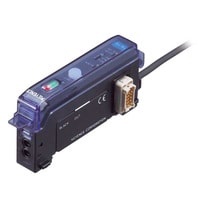
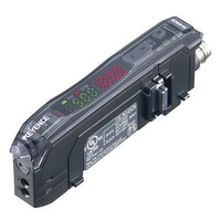
Fibre Amplifier, Zero-line Expansion Unit
Keyence FS-T0
Manual-Calibration Fibreoptic Sensor FS-V/T/M series
Categories: Fibre Optic Sensors, Sensors
GET A PRICE
To receive a proposal, please send your request to info@sensors-trade.com and specify the required positions and company details.
Specification
| Model | FS-T0 | |
| Type | 0-line expansion unit | |
| Output | - | |
| Light source | Red LED | |
| Sensitivity adjustment/Mode selection | Button | |
| Response time | 410 µs to 1 ms*1 | |
| Operation mode | LIGHT-ON/DARK-ON (switch-selectable) | |
| Indicator lamp | Output indicator: Red LED, Stable operation indicator: Green LED Calibration indicator: Orange LED | |
| Timer function | ON-delay: 40 ms/OFF-delay: 40 ms/Timer OFF (switch-selectable) | |
| Input | Non-voltage input (contact, solid state) | |
| Control output | ? | |
| Stability output | ||
| Protection circuit | Reversed polarity protection, Overcurrent protection, Surge absorber | |
| Unit expansion | Up to 16 expansion units can be connected (a total of 17 units)*2 | |
| Mutual interference suppression | FINE : 4, TURBO/SUPER: 8 | |
| Rating | Power voltage | 12 to 24 VDC ±10 %, Ripple (P-P) 10 % or less*3 |
| Current consumption | 35 mA or less | |
| Environmental resistance | Ambient light | Incandescent lamp: 10,000 lux max., Sunlight: 20,000 lux max. |
| Ambient temperature | -10 to +55 °C (No freezing)*4 | |
| Relative humidity | 35 to 85 % RH (No condensation) | |
| Vibration resistance | 10 to 55 Hz, Double amplitude 1.5 mm, 2 hours in each of the X, Y, and Z directions | |
| Shock resistance | 500 m/s2, 3 times in each of the X, Y, and Z directions | |
| Case material | Polycarbonate | |
| Weight | Approx. 20 g | |
| *1 The response speed varies depending on the number of expansion units connected. *2 If more than one unit is used together, the ambient temperature varies with the conditions below. Mount the units on the DIN rail with mounting brackets and check that the output current is 20 mA or less. 3 to 10 Units: -10 to +50°C (14 to 122°F), 11 to 16 Units: -10 to +45°C (14 to 113°F) *3 Power to the FS-T2/T0/M2/M0 is supplied through the FS-T1/M1/V1/V11/R0, PS-T1, LV-21A/11A or CZ-V1. *4 When extended, the ambient usage temperature varies according to the following conditions. Be sure to mount units on a DIN rail (attached to a metal plate) and ensure that the output current is 20 mA or less. When extended |


