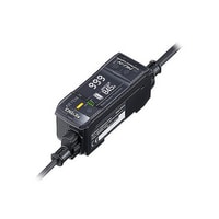
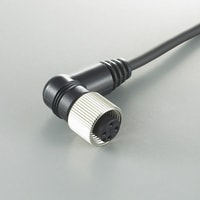
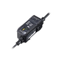
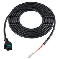
Multi-Sensor Controller, Expansion Unit
Keyence MU-N12
Clamp-on Flow Sensor FD-Q series
Categories: Flow Sensors, Process Controls / Process Sensors
GET A PRICE
To receive a proposal, please send your request to info@sensors-trade.com and specify the required positions and company details.
Specification
| Model | MU-N12 | |
| Main unit/Expansion unit | Expansion unit | |
| Response time | Depends on the connected sensor model*1 | |
| Power supply | Power supply voltage | 24 VDC, ripple (P-P) 10% or less, Class 2 or LPS |
| Current consumption | 55 mA or less (without load)*2 | |
| I/O | Control output | 4 max., NPN open collector/PNP open collector selectable, 24 V or less, Main unit: 50 mA or less*3, Expansion unit: 20 mA or less, Residual voltage: 2 V or less, N.O./N.C. selectable *1*4 |
| External input | 5 max., Short-circuit current: NPN: 1 mA or less, PNP: 2 mA or less, For the applied voltage, see wiring diagrams (page 3 of the instruction manual) *1*4 | |
| Analogue output | - | |
| Protection circuit | Protection against reverse power connection, power supply surge, output overcurrent, output surge, and reverse output connection | |
| Expansion units | Up to 4 expansion units*5 | |
| Sensor connection specification | Allowable sensor current | 150 mA or less |
| N-bus connection specification | Allowable passing current | 900 mA or less |
| Environmental resistance | Ambient temperature | -20 to +50 °C (No freezing) |
| Relative humidity | 35 to 85 % RH (No condensation) | |
| Vibration resistance | 10 to 55 Hz, Double amplitude 1.5 mm, 2 hours in each of the X, Y, and Z directions | |
| Shock resistance | 1,000 m/s2, 6 times in each of the X, Y, and Z directions | |
| Material | Case and dust cover: Polycarbonate Buttons: Polyacetal Display panel: PMMA | |
| Weight | Approx. 70 g | |
| *1 The response time, as well as the types and number of inputs and outputs that are available, vary depending on the connected sensor model. For details, see the specific "MU-N Series User's Manual" for the model that will be connected. *2 1185 mA or less when a sensor is attached, 4 outputs (with loads) are used, and expansion units are connected. *3 20 mA or less: When using the expansion unit. *4 For more information on Control output, External input, and Analog output wire allocation, please refer to the table of "Power Cable Pin Layout" on page 3 of this manual. *5 Up to 5 N-bus devices, including the main unit (or network unit), can be linked together. |


